Table of Contents
Introduction to Standard Penetration Test (SPT)
Penetration tests are the oldest and most common form of in situ tests and involve pushing or driving a rod, point, or sampler into the ground to delineate soft zones from firm zones.
The SPT is a Dynamic Penetration Test in which the resistance to the driving and installation of a thick-walled tube is measured. At the same time, the test is a sampling technique in which a sample of the soil through which the penetration takes place is obtained. It is the only in situ test that provides a sample for soil classification and other index testing, an attribute that many engineers feel is a distinct advantage of the test and one that sets the test apart from all others.
The SPT has some advantageous attributes that make it useful for many routine site investigations:
1. The test concept, arrangement, and equipment are relatively simple, robust, and inexpensive;
2. The equipment is readily available from most drillers around the world and is easily adaptable to most drill rigs;
3. The procedure is relatively easy to carry out, and testing may be performed at reasonably frequent intervals, often being performed continuously in the upper layers of soil or the primary zone of influence for foundations;
4. A soil sample is usually obtained for visual/manual identification and index property evaluation;
5. The test has a wide range of applicability, from weathered rock and gravelly sands to soft insensitive clay;
6. The test data are simple to collect and the test results are reduced rapidly in the field.
There is also an argument by some engineers that the SPT is a “one-number test”, that is, the SPT only gives a single number to use in assessing soil behavior.
Mechanics of The Standard Penetration Test
The test procedure calls for the input of specified impact energy to drive a split tube soil sampling barrel of specified dimensions a required distance. The test consists of a falling weight or hammer of mass 63.5kg (140 lbs) that is allowed to drop (free-fall) a distance of 0.76m (30in.) to strike an anvil. The anvil is connected to a set of drill rods that extend to the depth of testing/sampling. A sampling barrel, usually called a split spoon, is attached to the end of the drill rods and is advanced into the soil with each impact of the hammer.
In typical practice, chalk marks are made on the drill string to mark off three 0.15m (6in.) increments; the hammer is raised and dropped; the number of hammer blows to advance the spoon each 0.15m (6in.) increment are recorded as N0–6; N6–12; and N12–18. The initial 0.15m (6in.) penetration is considered by ASTM as a “seating” penetration and the sum of the hammer blows for the second two 0.15m (6in.) increments is called the SPT N value (with units of blows per 0.3m or blows per ft) and is the reference measurement obtained from the test. It is important that the incremental blow count values for each 0.15m (6in.) be recorded and reported, which is actually required by ASTM D1586.
In the event the full 0.46m (18in.) of penetration cannot be achieved, ASTM D1586 allows the test to be terminated if:
1. A total of 50 hammer blows have been applied during any one of the three 0.15m (6in.) increments;
2. A total of 100 hammer blows have been applied; or
3. There is no observed advance of the sampler during the application of ten successive hammer blows.
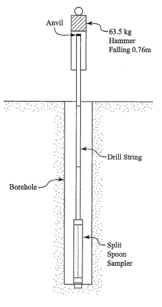
Equipment of Standard Penetration Test
The mechanics of the SPT described in the previous section represent a relatively simple concept; however, because the test is perceived as being so simple, the execution of the test may vary widely. This is a result of the variations in test equipment that have been available and are currently being used in the field to conduct the test. The test equipment consists of four basic components: the drop weight or hammer with an anvil, a string of drill rods connecting the sampler to the hammer, and a barrel sampler.
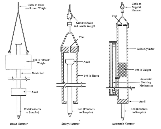
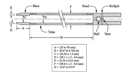
Standard Penetration Test Procedures
The test procedures and equipment for conducting the SPT are described in detail in ASTM D1586 Standard Test Method for Penetration Test and Split-Barrel Sampling of Soils and in ASTM D6066 Standard Practice for Determining the Normalized Penetration Resistance of Sands for Evaluation of Liquefaction Potential. The SPT is also an international reference test and described in ISO 22476-3:2005 Geotechnical Investigation
and Testing–Field Testing–Part 3: Standard Penetration Test.
Factors Affecting Standard Penetration Test Results
The goal of the SPT is to have the response from the test reflect differences in soil behavior, not differences in the test procedure. There are a number of factors that can affect the results of the SPT. Because of the historical variability in drilling equipment, techniques, personnel, etc., and the more or less crude fashion in which the test was performed, the results tended to show a high degree of variability. Drop hammer systems using a rope and cathead tend to give erratic results simply because the energy is largely uncontrolled and varies widely from drop to drop. However, many of these issues have been eliminated by using a calibrated automatic hammer. There are three reasons that only calibrated hammers should be used to conduct the SPT:
1. Automatic hammers provide a repeatable operator independent known energy level;
2. A fully enclosed automatic hammer is much safer for the drill crew;
3. Automatic hammers provide increased productivity in the drilling operation.
Affecting Factors:
- Energy Delivered to the Sampler. A number of early investigations showed that the most signifcant factor affecting the N-value from the SPT as the amount of energy delivered to the sampler.
- SPT Hammer Energy Calibration. ASTM D4633 provides a recommended procedure for performing the energy calibration of the SPT.
- Other Factors Affecting SPT Results Including Diameter of Drill Rods, Drill Rod Length, Sampler Dimensions, Diameter of Borehole, Method of Drilling/Drilling Fluid, Cleanout of the Borehole, Rate of Testing, Seating of the Spoon and Condition of the Drive Shoe.
Corrections to SPT Blow Counts
Because the SPT blow count is directly related to the hammer system energy, it is necessary to adjust the results of the test to a standard energy level. This will allow a proper comparison of test results so that different hammer systems can be compared, and proper interpretation of the test data can be made. Corrections to the field SPT N-value are made to account for hammer energy, rod length, borehole diameter, and sampler geometry.
Corrections for Hammer Energy, Equipment, and Drilling: N to N60
Based on several suggestions, a reference value of 60% of the theoretical free-fall energy is
used to adjust N-values to a common reference point.
N60 = N × ER × CB × CS × CR
where
N60 = energy and procedure-corrected blow count
N = field-measured blow count
ER = energy ratio = ES/E60
ES = energy of the system
CB = correction factor for borehole diameter
CS = correction factor for sampler geometry
CR = correction factor for rod length
Comparison of uncorrected and corrected N-values
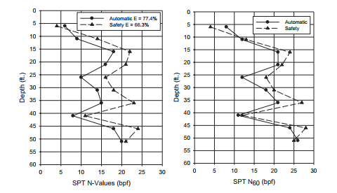
Correction for Overburden Stress in Sands: N60 to (N1)60
In a uniform sand deposit with a constant void ratio or relative density, the SPT N-value will increase with depth as the mean effective stress increases with depth. Therefore, the N-value must be corrected for the influence of this changing stress level to give a single characteristic value that describes a single relative density.
(N1)60 = CN × N60
where
N60 = energy-corrected blow count
(N1)60 = corrected blow count to a standard vertical effective stress level
CN = vertical effective stress correction factor
Interpretation of Soil Properties from SPT Blow Counts
A number of suggestions have been made for using SPT results to predict individual soil properties. The SPT has applications in a wide range of soils; however, correlations between the test results and soil properties can be divided into either coarse-grained or fine-grained soils.
SPT Correlations Software
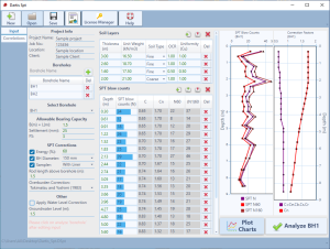
Dartis SPT is a powerful, user-friendly software for correlating soil properties from SPT blow counts. We have gone through many papers and geotechnical reference books and collected over 200 SPT correlations with various soil properties.
Every correlation is developed for certain soil. Dartis SPT knows that. At a specific depth, based on the site stratigraphy Dartis SPT only uses the correlations that are developed for that type of soil. We have categorized the soil types as Coarse and Fine-Grained, Coarse-Grained and Fine-Grained. Each correlation may be valid for one of above.
Explore the extensive features of Dartis SPT and download a trial version today.
Summary of SPT
The SPT can be a useful in situ test, provided that engineers carefully control the test. The test results can be reliable if the equipment and procedures are controlled. The following procedure for performing the SPT is suggested:
1. Use a calibrated automatic hammer set to a test rate of 30–40 blows/min;
2. Use NW or AW (square or tapered thread) drill rods in lengths of 3.0m (10ft);
3. Use a 0.61 (24in.)-long split spoon without liners with an internal shoe diameter of 34.9mm (1.375in.) and an internal barrel diameter of 38.1mm (1.5in.);
4. With the rods touching the bottom of the borehole but still being held, carefully mark three 0.15m (6in.) drive increments;
5. Drive the spoon a total of 0.46m (18in.) and record incremental blow counts for each 0.15m (6in.) increment;
6. Use only solid-stem or hollow-stem augers with an internal diameter not greater than 107.9mm (4.25in.) or 100mm (4in.) rotary wash boring to advance the borehole;
7. In coarse-grained soils below the water table, use drilling mud full depth inside the hollow stem augers or casing;
8. Always record the sample recovery;
